new and used avionics
 Sell Your Avionics Here
|
Avionics List
new and used avionics |
Sell Your Avionics Here
|
Buying Safety Tips |
Avionics Articles and Reviews
|
We don't hear the word glideslope mentioned as often as you
did in the past; today's buzzwords are GPS, WAAS, MFD, TCAD and the
list goes on and on.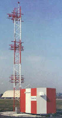 There's a couple of reasons we don't include glideslope in our
buzzwords nowadays; one is the system works great and with modern radios
such as the King KX-155 there's seldom a glideslope problem related
with the equipment or the ground station. Another reason we don't talk
about glideslope is because it's boring. You can't "crank
in" a glideslope frequency, listen to the ident or turn the knob on
the CDI and make the needle move. You may find this interesting; while
you must check your VOR's for accuracy every 30 days (FAR 91.171) for
IFR operation, there is no requirement for part 91 operators (GA guys)
to ever have the glideslope system tested for accuracy. Imagine, an
instrument that can get you within 200ft of the ground in most cases but
it never has to be checked to verify proper operation. Why not you ask?
To be honest I haven't a clue but I personally believe the system
should be tested anytime you are in the avionics shop for your bi-annual
transponder test. While the glideslope may not have the flashing lights
and pizzazz such as the panel-mounted GPS or MFD, it's still the only
legal electronic vertical navigation today in the general aviation
world. By the way, the word glideslope is not mentioned in Mr. Webster's
dictionary; as far as I could determine, it's exclusively an aviation
term.
There's a couple of reasons we don't include glideslope in our
buzzwords nowadays; one is the system works great and with modern radios
such as the King KX-155 there's seldom a glideslope problem related
with the equipment or the ground station. Another reason we don't talk
about glideslope is because it's boring. You can't "crank
in" a glideslope frequency, listen to the ident or turn the knob on
the CDI and make the needle move. You may find this interesting; while
you must check your VOR's for accuracy every 30 days (FAR 91.171) for
IFR operation, there is no requirement for part 91 operators (GA guys)
to ever have the glideslope system tested for accuracy. Imagine, an
instrument that can get you within 200ft of the ground in most cases but
it never has to be checked to verify proper operation. Why not you ask?
To be honest I haven't a clue but I personally believe the system
should be tested anytime you are in the avionics shop for your bi-annual
transponder test. While the glideslope may not have the flashing lights
and pizzazz such as the panel-mounted GPS or MFD, it's still the only
legal electronic vertical navigation today in the general aviation
world. By the way, the word glideslope is not mentioned in Mr. Webster's
dictionary; as far as I could determine, it's exclusively an aviation
term.
The Glideslope System. The glideslope signal is radiated via an antenna array located in the general area of the approach runway, a vertical tower about 20' tall. The signal is radiated to produce two intersecting lobes, one on top of the other. The upper lobe is modulated with a 90-hertz and the bottom is modulated with 150-hertz. These lobes are transmitted from the end of the approach runway outward at an angle between 2.5 3.3 degrees. There's a big difference in flying a 2.5 versus a 3.3 degree glideslope, discuss this with your instructor. When the aircraft glideslope receiver is receiving equal amounts of 90 and 150-hertz signal, the glide path is defined and the glideslope needle is centered. Based on this format, the glideslope provides the pilot with vertical guidance to an altitude (MAP) determined by the FAA.
If the aircraft is above the glide path then the receiver is
receiving more of 90-hertz signal than 150 hertz and glideslope needle
will be below the center position within the indicator;
alerting the pilot that he/she is above the glideslope and needs to
increase the descent rate. If the aircraft is below glide path, the
receiver is now receiving more 150-hertz signal than 90-hertz signal and
needle will move toward the top of the indicator telling the pilot to
fly up.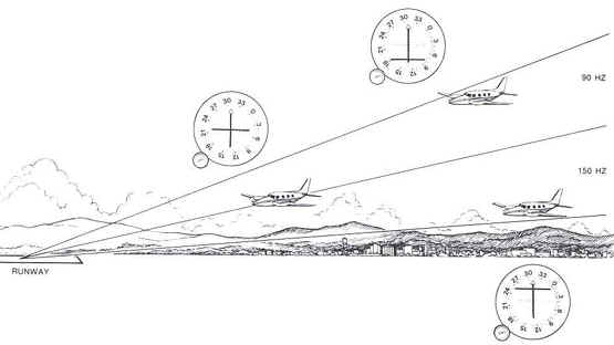 I know you keep a centered glideslope needle throughout the
approach but I wanted to tell you what you would see just in case you
fly with someone who flies off the glide path... From what you just
read, one can easily determine that the glideslope system is a simple
system.
I know you keep a centered glideslope needle throughout the
approach but I wanted to tell you what you would see just in case you
fly with someone who flies off the glide path... From what you just
read, one can easily determine that the glideslope system is a simple
system.
A glideslope is always paired with a localizer; both the localizer and glideslope needles and flags are located within the same indicator. There is a glideslope flag also. If a problem occurrs within the aircraft glideslope receiver or the radiated signal from the ground becomes a problem, the warning flag will be in view. Anytime there is a flag in view you MUST assume there is a problem and not rely on the signal. In other words if you have a glideslope flag in view, DO NOT use the information on the indicator even if it appears to be displaying what you think is proper information. There are procedures that must be followed if a glideslope flag is in view. Please consult your favorite CFII for details. Another thing, NEVER use a glideslope data on a back course, again talk to an instructor as to why not.
How do you "Tune In" a glideslope frequency you ask?
Hmm, there's not an extra set of knobs on the navigation receiver to
tune the glideslope, nor is there a glideslope frequency on the approach
plate. OK, grab a cold glass of milk and some Oreo cookies and lets
discuss the process. Localizer and glideslope frequencies are what we
call "Paired" frequencies. When you tune in the ILS frequency
called out on your approach plate you are in fact tuning the glideslope,
you just don't know what that frequency is. Because the frequencies
are paired, when you tune to the ILS frequency of 108.90 MHz, the
navigation receiver automatically tunes the glideslope receiver to
329.30MHz. Our VOR and localizer frequencies are in what we call the VHF
(Very High Frequency) band; glideslope frequencies are in the UHF
(Ultra-High Frequency) band. If you look at a paired frequency chart;
you would notice that the glideslope frequency doesn't necessarily
increase as you tune in a higher ILS frequency. The reason for this is
the glideslope frequency selected is paired with that particular
localizer frequency so not to cause interference. In other words the UHF
and VHF frequency are paired so not to cause any type of interference
that would distort the other. By the way, there 40 ILS frequencies
available. Normally you be able to receive a glideslope signal 10 miles
out or more. Be advised you may not receive a valid glideslope signal
unless your aircraft is on the localizer and heading for the proper
runway, more on this later. Another point to keep in mind is the closer
you get to the runway, the more sensitive the needle is which increases
the pilot workload to keep it centered. High performance autopilots such
as the S-Tec System 55X and King KFC-200 will capture and track the
glideslope;
they do a pretty good job of keeping the needle centered; much better
than Mike Busch but not as good as yours truly.
OK, grab a cold glass of milk and some Oreo cookies and lets
discuss the process. Localizer and glideslope frequencies are what we
call "Paired" frequencies. When you tune in the ILS frequency
called out on your approach plate you are in fact tuning the glideslope,
you just don't know what that frequency is. Because the frequencies
are paired, when you tune to the ILS frequency of 108.90 MHz, the
navigation receiver automatically tunes the glideslope receiver to
329.30MHz. Our VOR and localizer frequencies are in what we call the VHF
(Very High Frequency) band; glideslope frequencies are in the UHF
(Ultra-High Frequency) band. If you look at a paired frequency chart;
you would notice that the glideslope frequency doesn't necessarily
increase as you tune in a higher ILS frequency. The reason for this is
the glideslope frequency selected is paired with that particular
localizer frequency so not to cause interference. In other words the UHF
and VHF frequency are paired so not to cause any type of interference
that would distort the other. By the way, there 40 ILS frequencies
available. Normally you be able to receive a glideslope signal 10 miles
out or more. Be advised you may not receive a valid glideslope signal
unless your aircraft is on the localizer and heading for the proper
runway, more on this later. Another point to keep in mind is the closer
you get to the runway, the more sensitive the needle is which increases
the pilot workload to keep it centered. High performance autopilots such
as the S-Tec System 55X and King KFC-200 will capture and track the
glideslope;
they do a pretty good job of keeping the needle centered; much better
than Mike Busch but not as good as yours truly.
In the old days, glideslope receivers were large, remote boxes
that weighed several pounds and took a lot of space. Modern radios such
as UPSAT,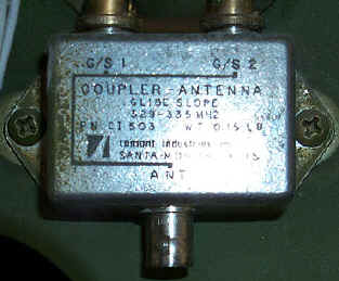 Garmin and Narco have the glideslope built inside the
panel-mounted box; it weighs just a few ounces. Some of the older
equipment had the glideslope receiver built inside the indicator such as
the King KI-214, normally these are problem children and should be
avoided by any serious instrument pilot. With few exceptions a single
glideslope receiver can drive several indicators along with the
autopilot.
Garmin and Narco have the glideslope built inside the
panel-mounted box; it weighs just a few ounces. Some of the older
equipment had the glideslope receiver built inside the indicator such as
the King KI-214, normally these are problem children and should be
avoided by any serious instrument pilot. With few exceptions a single
glideslope receiver can drive several indicators along with the
autopilot.
The glideslope antenna. One of the advantages of using UHF
frequencies for glideslope operation is only a small antenna and ground
plane is required. As a rule of thumb, the higher the frequency, the
smaller the antenna can to be. For instance, note how long your VHF COM
antenna is versus the size of the GPS antenna. Piper, Mooney, Beechcraft
for most parts used the standard navigation antenna located at the top
of the vertical stabilizer for the glideslope antenna. This antenna
picks up both the VHF Nav channels along with the paired glideslope.
Near the radio stack is what we call a splitter, which takes the UHF
signal and sends it to the glideslope and also takes the VHF signal and
sends it to the navigation receiver. Notice that I didn't mention
Cessna with the aircraft manufacturers listed above. Cessna installed
the glideslope antenna in the wing on some 210's, which cost a bundle
to replace when it failed but didn't work any better than the antenna
on the vertical stabilizer. Then they placed the antenna in the
windscreen, thinking it would have an unrestricted shot at the
glideslope ground array. This system performs poorly under some
conditions; Cessna even stated in the POH to avoid some RPM ranges to
"avoid oscillations of the glideslope deviation pointer caused by
propeller interference". If I submitted a flight manual supplement
to the FAA with a note such as mentioned above;
the FAA would be all over me. All Cessna aircraft with ARC radios used a
remote glideslope receiver; here's another weird thing Cessna did. The
mounted the glideslope receiver in the tail of the aircraft on many of
their models. This is how it worked: The antenna is located on the
vertical stabilizer and a cable runs from the top of the stabilizer to
the splitter, which is located under the instrument panel.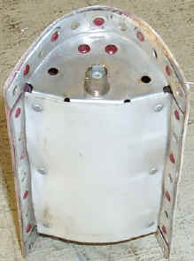 From the
splitter a cable runs back to the glideslope receiver in the tail of the
aircraft. In layman's terms, that's a lot of loss due to the long
cable runs. Cessna finally started using the standard navigation antenna
for glideslope like most manufacturers have done for years. Large
twin-engine aircraft normally have the glideslope antenna behind the
radome. Jets normally have a segregated glideslope antenna some where
near the front of the aircraft. The UPSAT SL30 uses regular VHF input
and takes the glideslope signal from that input inside their box, thus
no splitter is required.
From the
splitter a cable runs back to the glideslope receiver in the tail of the
aircraft. In layman's terms, that's a lot of loss due to the long
cable runs. Cessna finally started using the standard navigation antenna
for glideslope like most manufacturers have done for years. Large
twin-engine aircraft normally have the glideslope antenna behind the
radome. Jets normally have a segregated glideslope antenna some where
near the front of the aircraft. The UPSAT SL30 uses regular VHF input
and takes the glideslope signal from that input inside their box, thus
no splitter is required.
Glideslope has been around for decades; it works great and gets us lower on the approach than any other product out there today. How long will glideslope be around you ask? Different folks give us different answers; I'd be willing to bet it still be our main source of vertical navigation well into the 21st century. While the glideslope isn't high-tech it is a valuable tool to the instrument pilot.